DIP-40 · 8520A-1 · drawing, not a photo
Amiga chipsCommodore (MOS / CSG)
1985
CIA 8520
The ports chip: keyboard, floppy, parallel port, LED and timers. Every Amiga has two.
The CIA 8520 is the Amiga's input/output chip, inherited from the Commodore 64's 6526. Each machine has two: CIA-A reads the keyboard and the parallel port, lights the LED and moves the ROM out of the way at start-up; CIA-B drives the floppy drive and the serial port's control lines. Each one also has two timers and an event counter.
- 8
A Commodore 64 chip that stayed in the Amiga
CIA stands for Complex Interface Adapter. The original design is MOS Technology's 6526, the ports chip of the Commodore 64, which carries two. When Commodore designed the Amiga, rather than create an I/O chip from scratch it adapted what it already had: the 8520 is a 6526 with one difference, the time-of-day clock. In the 6526 it is a real clock, with hours, minutes and seconds in BCD; in the 8520 it became a plain 24-bit binary counter that counts pulses. Otherwise it is the same chip.
Commodore's internal specification, drawing 318029, describes it as a peripheral compatible with the 65xx bus, in a 40-pin package, and lists where it was used: the Amiga and the 1581 disk drive. Of the Commodore chips in the Amiga it is the only one not designed for it, and it speaks the language of the 65xx inside a 68000 machine: the processor has a clock of its own for these peripherals, the E clock, at one tenth of its speed, and that is what the CIA synchronises to.
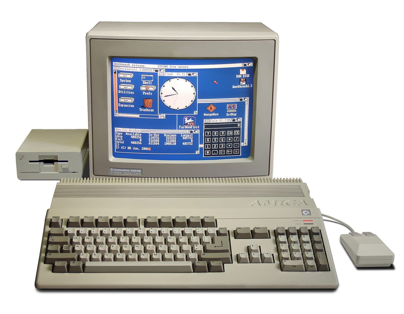
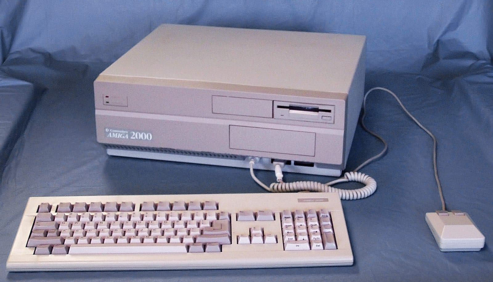
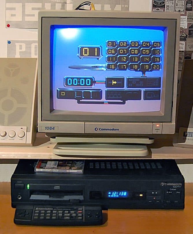
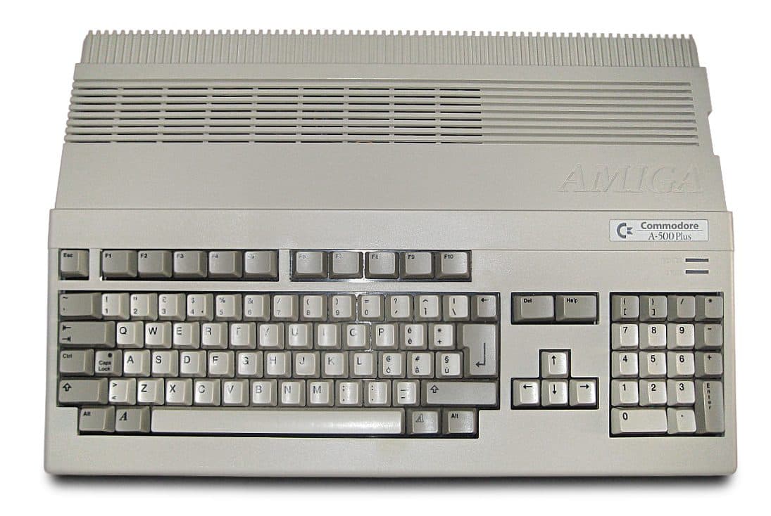
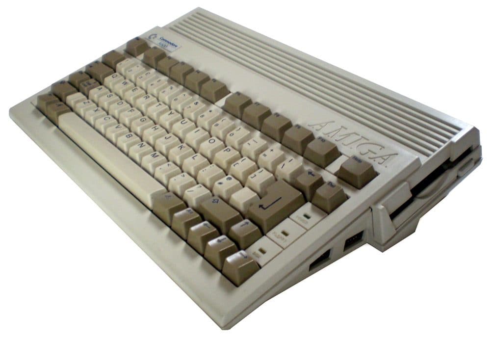
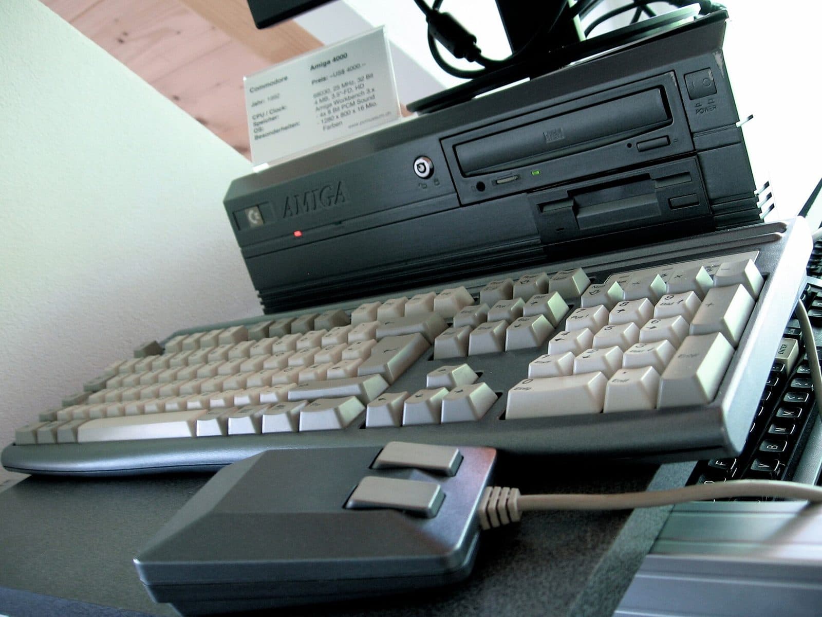
There are two in every Amiga, from the A1000 to the A4000, and the system calls them CIA-A and CIA-B. The exception is the CD32: Akiko absorbed their functions, and the console's board has none.
Two chips, two jobs
Each CIA has 16 input/output pins, in two 8-bit ports, plus a serial shift register, a pulse pin and an edge-detecting input. The Amiga splits the tasks between the two. CIA-A, at the odd addresses from $BFE001, has its whole port B given over to the 8 data bits of the parallel port, and port A full of loose bits: OVL, which puts the ROM at address zero; the power LED, which lights when the bit is zero; four floppy status signals (ready, track zero, write-protected, disk changed); and the fire buttons of the two game ports. Its serial register receives the keyboard.
CIA-B, at the even addresses from $BFD000, has its whole port B driving the floppy drive: motor, selection of one of four drives, step, direction and side. Port A gathers the serial port's flow-control lines (DTR, RTS, CTS, DSR, carrier detect) and the parallel port's control lines (BUSY, POUT, SEL). Its edge input counts the floppy's index pulses, once per revolution. CIA-B's serial register is not used for anything.
Each talks to the processor on its own interrupt level: CIA-A on level 2, CIA-B on level 6. And the two share a design quirk: CIA-A is wired to the low 8 bits of the data bus and CIA-B to the high 8 bits, so one's addresses are odd and the other's even, and they can only be accessed a byte at a time.
- Keyboard
- Floppy drive
- Parallel port
- Serial port (flow control)
- System: OVL and LED
- Game port fire buttons
Every pin of ports A and B, with the signal the Amiga wires to it. Source: Amiga Hardware Reference Manual, appendix F. Click a signal to see it lit up on the Amiga 500 rev 8A board, in the explorer.
How a key reaches the processor
The Amiga keyboard has a microcontroller of its own and connects to the machine by four wires: power, ground, KCLK (the clock, keyboard to computer only) and KDAT (the data, in both directions). Each key produces a 7-bit code, and the eighth bit says whether it was pressed (0) or released (1). The keyboard sends the 8 bits one by one on KDAT, with a pulse on KCLK for each bit, at about 60 microseconds per bit: a key takes half a millisecond to arrive.
On the Amiga's side, the receiver is CIA-A's serial shift register: KDAT comes in on the SP pin and KCLK on CNT. On the eighth pulse the byte drops into the data register and the CIA raises an interrupt. The software reads the code and has to answer: it pulls KDAT low for 85 microseconds, the handshake that tells the keyboard it may send the next key.
Two details show the care in the design. The line is active low, so the bits arrive inverted. And the byte goes out rotated: bit 6 is sent first and bit 7, the pressed-or-released bit, last. If the keyboard and the computer lose sync, the keyboard sends ones until it gets the handshake, and a garbage byte full of ones reads as a key release, which harms no one. Then it warns with a special code ($F9) and repeats the lost key. Try it in the demonstration further down.
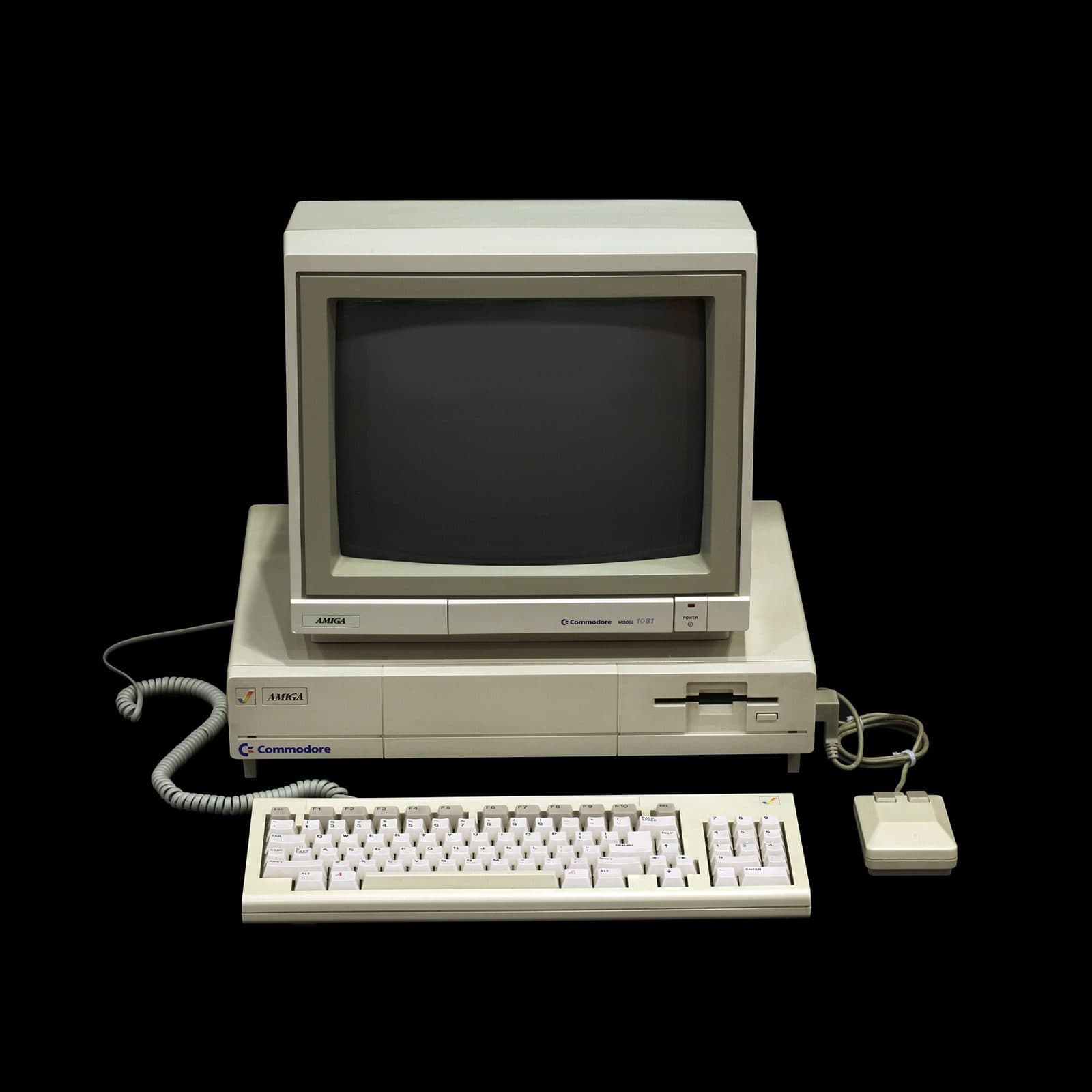 Amiga 1000 · 1985
Timers and the event counter
Each CIA has two 16-bit timers. You load a value, the timer counts down at the rate of the processor's E clock (709,379 times a second in PAL, 715,909 in NTSC, one tenth of the 68000's clock) and, when it reaches zero, it interrupts and reloads. They can be chained for 32-bit counts, count external pulses on the CNT pin, or put their output on a port B pin. They are what AmigaOS measures time with.
The third counter is the TOD, which in the 6526 was the time-of-day clock. In the Amiga it gained two clever uses: CIA-A's counts the 50 or 60 Hz pulses of each frame, and CIA-B's counts the screen's lines, 15,625 a second in PAL. Both have an alarm that interrupts when the counter reaches a chosen value. Being 24-bit counters, CIA-B's wraps round every 18 minutes, and CIA-A's after almost four days.
All told, each CIA has five interrupt sources: the two timers, the alarm, the serial register and the edge input. A single register, the ICR, says which one fired, and reading it clears it, so whoever reads it has to deal with everything that was there. Under AmigaOS, programs do not touch the CIAs directly: they ask cia.resource for timers and interrupts, and it shares out what there is between the system and whoever asks.
First to wake up
At power-on the CIA is among the first chips that matter. A reset makes every pin an input, and since they have pull-up resistors they read as one. That includes OVL, bit 0 of CIA-A's port A: at one, the Kickstart ROM appears at address zero, where the 68000 fetches its stack pointer and starting address. It is the only way the processor can start, because address zero is normally Chip RAM. Once running, Kickstart configures the two output bits (OVL and LED) and drops OVL: RAM returns to address zero and the ROM stays only in its own place, at the top of memory.
The same LED bit controls the sound's low-pass filter: that is why, when a game or a demo switches the filter off, the power LED dims. The Paula page explains the filter; this is the switch.
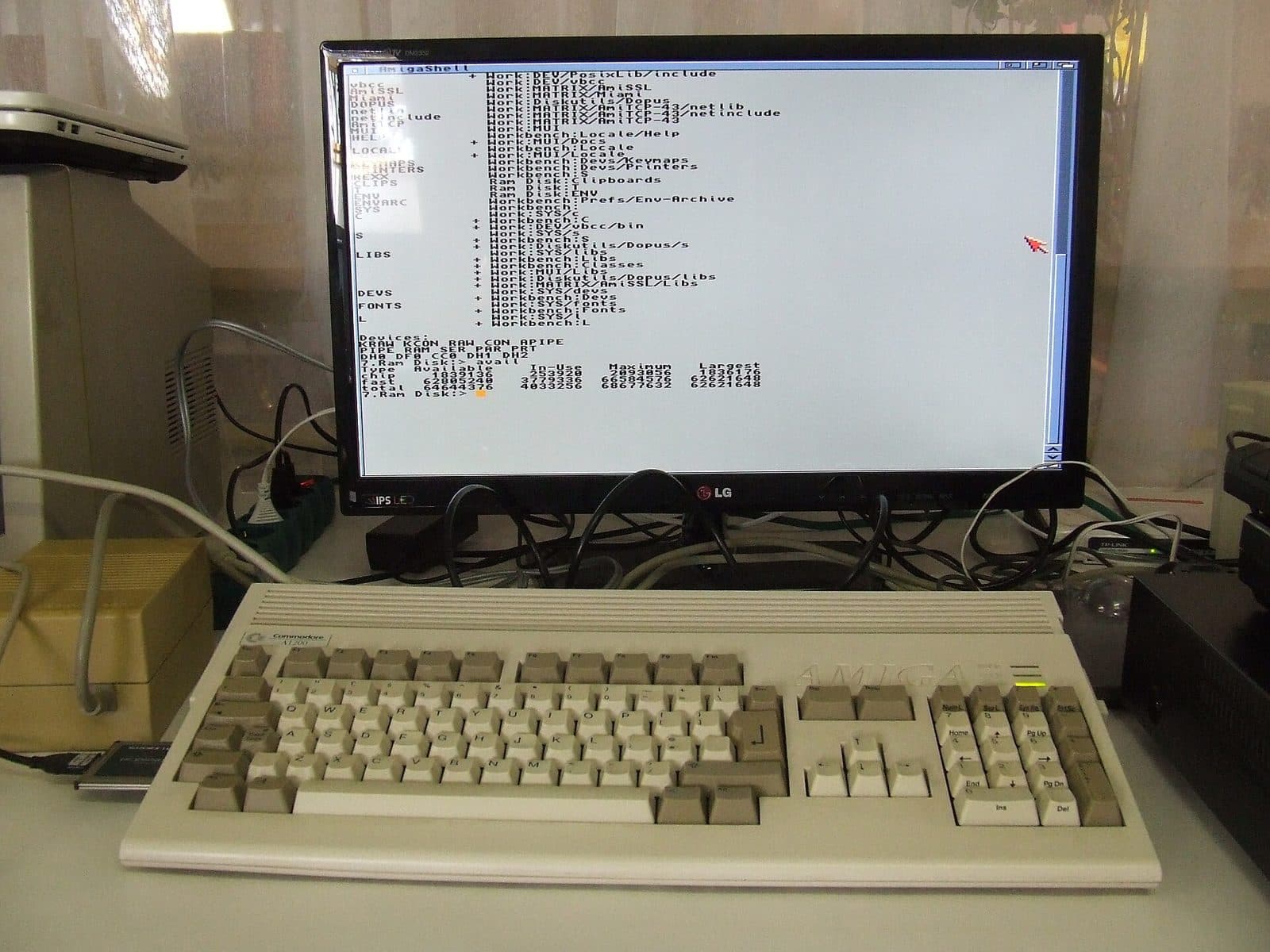
The package changed over the years. In the A1000, A500, A2000 and A3000 the 8520 is a 40-pin DIP, almost always socketed. In the A600, A1200 and A4000 it is a 44-pin PLCC soldered to the board. The CD32 has none. Inside, it was always the same 1985 chip.
Did you know…
The address $BFE001 is one of the Amiga's best known: it is the register you write to put out the LED, switch off the sound filter and hide the ROM.
A key takes about half a millisecond to reach the CIA: eight bits at 60 microseconds each, around 17 kbit/s.
The keyboard sends the pressed-or-released bit last on purpose: if it loses sync, the garbage that arrives reads as a key release, which is harmless.
Press Ctrl-Amiga-Amiga on an A1000 or some A2000s and you first get a warning code ($78): the keyboard announces that it will reset ten seconds later.
CIA-B's event counter counts screen lines, 15,625 a second in PAL, and wraps its 24 bits every 18 minutes.
CIA-B's serial register is not used for anything: every Amiga has a synchronous serial port asleep inside the chip.
Caps Lock is the only key that sends a code only when pressed: the pressed-or-released bit then says whether the light went on or off.
Key by key down the wire
The Amiga keyboard sends each key as 8 serial bits: 7 of code and 1 that says whether it was pressed or released, last. CIA-A takes them into its shift register and, at the end, the Amiga pulls the KDAT line low for 85 µs, the handshake that asks for the next key. Press a key on your keyboard, or one of these.
Click here and press a key
Bits on the wire, in the order 6-5-4-3-2-1-0-7 (line active low)
—
Protocol and codes: Amiga Hardware Reference Manual, appendix G.
Faults it is part of
Diagnostic guides from the board explorer that measure this chip's signals, board by board.
Keyboard doesn’t respond
The machine boots but the keys do nothing. Keys reach CIA-A over a serial data line and a clock line.
Amiga 500 rev 8A →Amiga 600 rev 2A →Amiga 1200 rev 2B →Amiga 1200 rev 1D.1 →Amiga 4000 rev 2 →Amiga 4000 rev B →Amiga 4000T rev 4 →
Floppy won’t read
The internal drive doesn’t spin, doesn’t move the head, or spins but won’t read. CIA-B gives the drive its orders and Paula receives the data.
Amiga 500 rev 8A →Amiga 600 rev 2A →Amiga 1200 rev 2B →Amiga 1200 rev 1D.1 →Amiga 4000 rev 2 →Amiga 4000 rev B →Amiga 4000T rev 4 →
Where it's found

Sources
- [1]IC, LSI, Complex Interface Adapter 8520 — desenho 318029 rev. C (especificação interna) · Commodore · espelho funet dos documentos Commodore, 1987
- [2]Amiga Hardware Reference Manual, apêndice F: 8520 Complex Interface Adapters · Commodore-Amiga · Amiga Developer CD 2.1, 1991
- [3]Amiga Hardware Reference Manual, apêndice G: Keyboard Interface · Commodore-Amiga · Amiga Developer CD 2.1, 1991
- [4]MOS Technology CIA (6526 e 8520) · Wikipédia
- [5]CIA 8520 (números de peça e máquinas) · Big Book of Amiga Hardware